
Fiber Optic Fusion Splicing Machine Buying Guide: How to Choose a Splicer, Cleaver and OTDR

A fusion splicing machine can produce a beautiful-looking joint on its screen and still be the wrong investment for your work. Field conditions, fiber type, alignment method, cleaver quality, battery endurance, heating performance, local service and verification tools all influence real network results. The lowest purchase price may become expensive through repeat splices and downtime; the most advanced machine may be unnecessary for routine access-network work.
The right buying decision begins with the job. Are you building FTTH drops, maintaining metro links, working on long-haul networks, splicing ribbon fiber, restoring outages or supporting data centres? How many splices must a team complete each day? What are the acceptable loss limits, connector types and environmental conditions? The answers determine the splicer and the complete tool ecosystem around it.
Quick answer: Choose a fusion splicer by matching its alignment technology, supported fiber types, splice and heating performance, display and automation, battery capacity, ruggedness, electrode and consumable costs, calibration support and warranty to your actual projects. Never evaluate the splicer alone: a precision cleaver, correct holders, stripping and cleaning tools, splice sleeves, inspection equipment, optical power meter and OTDR are part of the quality system.
How a fiber optic fusion splicer works
Fusion splicing joins two prepared optical fibers by aligning their glass ends and applying a controlled electric arc. The machine analyses the fibers, positions them, performs the fusion and estimates splice loss. A heat-shrink protection sleeve is then shrunk over the joint to restore mechanical protection.
The process appears simple because modern splicers automate many steps. Yet the measured result depends on end-face quality, cleanliness, fiber geometry, alignment, arc condition and handling. A machine cannot fully compensate for a damaged stripper, contaminated V-groove or poor cleave.
Mechanical splicing is another method, using a precision alignment component and index-matching material rather than fusion. It can suit certain fast restoration or low-volume situations, but fusion is generally preferred where permanent, low-loss, high-reliability joints are required.
Core alignment vs cladding alignment
Cladding-alignment splicers
Cladding-alignment machines position fibers by referencing the outer glass geometry, commonly through V-grooves. They can be compact, quick and cost-effective for many access, enterprise and FTTH tasks using consistent single-mode fiber. They remain dependent on accurate preparation and the relationship between the cladding and optical core.
Core-alignment splicers
Core-alignment machines use imaging and positioning systems to align the light-carrying cores more directly. This can offer greater control for demanding networks, dissimilar fibers, older cables or situations where very low and repeatable loss is important. These machines are often more expensive and may require more specialised service.
The label alone does not determine field quality. Compare demonstrated repeatability, verified results, serviceability and performance on the fibers your team actually uses. A well-maintained cladding-alignment unit in trained hands can outperform a neglected premium machine.
Start with the fiber and network application
Confirm supported fiber categories and profiles rather than assuming “single mode” covers everything. Projects may involve standard single-mode, bend-insensitive fiber, multimode, dispersion-shifted types, pigtails, loose-tube fiber, drop cables or specialty constructions. Ribbon splicing needs a compatible ribbon machine, holders and cleaving system.
Also examine the link budget and restoration priority. A short building link and a long optical span have different tolerances. Networks with tight budgets or many cascaded splices may justify higher alignment capability and stronger test discipline. For emergency teams, startup time, battery condition and outdoor usability may matter as much as laboratory specifications.
Ten fusion splicer specifications that matter
• Alignment system: understand what the cameras and motors are aligning and for which fiber profiles.
• Splice-loss performance: treat catalogue figures as controlled-condition indicators; verify repeatability on your fiber.
• Splice and heat cycles: speed matters only if preparation, protection and testing remain consistent.
• Display and magnification: a bright, clear screen helps technicians inspect end faces and contamination.
• Automatic functions: useful features include fiber detection, focus, arc control, wind protection and program selection.
• Battery capacity: ask for realistic combined splice-and-heat cycles and the cost of a replacement battery.
• Environmental rating: consider dust, moisture, wind, shock, altitude and operating temperature for field use.
• Data and traceability: image storage, job records and export options can support quality control.
• Electrode life and maintenance: understand cleaning, replacement, stabilisation and arc-calibration routines.
• Local support: calibration capability, repair turnaround, spares, training and loan-unit policies reduce downtime risk.
Ask the supplier to demonstrate the unit using your common fiber, sleeves and field workflow. A live demonstration reveals holder convenience, menu clarity and heating consistency better than a specification sheet.
Why the fiber cleaver is as important as the splicer
A fusion splicer can align only the surfaces it receives. A poor cleave may produce an angled, chipped or irregular end face, causing higher loss, bubbles or repeated arc attempts. Frequent “bad splice” alarms often begin at preparation rather than inside the splicer.
Evaluate cleave-angle consistency, blade life, blade-position adjustment, waste-fiber collection, holder compatibility and ease of cleaning. Automatic or semi-automatic designs can improve workflow, but technique still matters. The operator should place the stripped fiber without twisting it, avoid touching the bare glass and close the cleaver smoothly.
A lower-cost cleaver that requires repeated attempts wastes fiber length, sleeves and technician time. Include replacement blades and authorised service in the total-cost calculation.
The complete fiber splicing toolkit
A professional kit normally extends beyond the machine and cleaver:
• Jacket, buffer and precision fiber strippers suited to the cable
• Approved high-purity cleaning fluid and lint-free wipes
• Fiber holders, clamps and drop-cable accessories
• Correct-length splice-protection sleeves and a sleeve organiser
• Visual fault locator for continuity and visible fault checks
• Optical power meter and light source for end-to-end loss measurement
• OTDR with suitable wavelength, dynamic range, launch cable and receive cable
• Connector inspection scope and approved cleaning tools
• Safe fiber-shard container, eye protection and a clean work surface
• Charging, spare battery and transport protection for field work
The exact list depends on whether the team handles construction, acceptance testing, troubleshooting or only splicing. Build a kit around the complete task, not the most visible machine.
OTDR, power meter and splicer estimate: three different signals
The loss estimate displayed by a fusion splicer is useful process feedback, but it is not a complete link-acceptance result. It is calculated from image and machine data rather than a direct end-to-end optical measurement.
An optical loss test set—typically a light source and power meter—measures link insertion loss. An OTDR sends pulses and analyses backscatter and reflections to estimate the distance and characteristics of events such as connectors, splices, bends and breaks. Bidirectional OTDR analysis may be required by a project specification to reduce measurement bias at dissimilar fibers or splice points.
Select OTDR wavelength, dynamic range, pulse width, dead-zone performance and launch/receive setup for the link. A powerful unit used with the wrong settings can hide near-end events or give a misleading trace. Training and interpretation are essential.
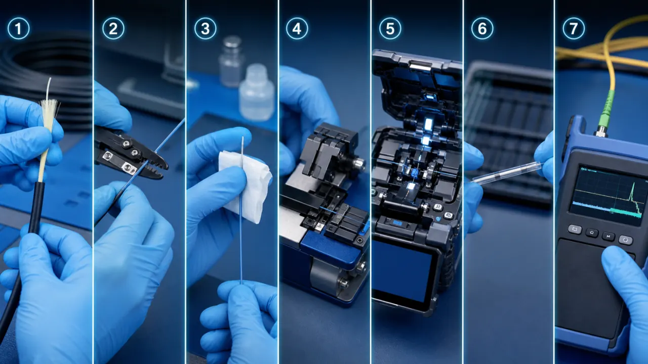
A reliable fusion splicing workflow
• Confirm the cable, fiber identification, splice plan and safety controls.
• Organise the enclosure and slide the protection sleeve onto one fiber before splicing.
• Strip the coating with a clean, undamaged tool.
• Clean the bare fiber using the approved method and avoid recontamination.
• Cleave to the required length and inspect the result.
• Place both fibers correctly in the holders or clamps without stress.
• Allow the machine to inspect, align and fuse; review warnings and estimated loss.
• Repeat only after diagnosing the cause—do not repeatedly arc a questionable joint.
• Centre the sleeve, heat it fully and allow it to cool without bending.
• Route the protected splice within its allowed bend radius and complete testing.
Standard operating procedures should define acceptable results, cleaning frequency, calibration checks, sleeve placement and recordkeeping. Consistency across technicians is a major network-quality advantage.
Maintenance that protects splice quality
Daily care includes cleaning V-grooves, clamps, lenses and the wind protector using the manufacturer-approved method. Inspect electrodes, cleaver blade, strippers, holders and heater condition. Never use hard metal tools on precision surfaces.
Arc calibration or stabilisation may be needed when electrodes are replaced, altitude or environment changes, or the manufacturer recommends it. Firmware and splice programs should be managed rather than changed casually. Batteries should be stored and cycled according to guidance.
Maintain a simple log for machine serial number, electrode count, calibration, faults, repairs and technician. This helps separate operator training issues from equipment deterioration.
Total cost of ownership: look beyond the purchase price
Compare the cost of electrodes, batteries, chargers, heaters, cleaver blades, holders, annual calibration, repair labour, transport and downtime. Check warranty exclusions and where repairs occur. A machine with local spares and trained support may offer better value than a cheaper imported unit that remains unavailable for weeks.
Also calculate productivity. Repeated preparation, failed heaters and unavailable batteries cost more than their consumables. Conversely, do not pay for specialty modes or connectivity that your work will never use.
Questions to ask a fusion splicer supplier
• Which fibers and cable formats are supported with supplied accessories?
• Is the alignment method demonstrated and documented?
• Can we perform a trial with our fiber and verify results independently?
• What training is included for splicing, maintenance and troubleshooting?
• Where are calibration and repairs performed, and what is typical turnaround?
• Are electrodes, batteries, cleaver blades and holders stocked locally?
• What data can be stored or exported for project records?
• What are the warranty period, exclusions and accidental-damage options?
Frequently asked questions
Which is better: core alignment or cladding alignment?
Core alignment is often preferred for demanding or varied applications, while cladding alignment can be effective and economical for consistent access-network work. The correct choice depends on fiber, link budget, volume, field conditions and support.
Does a low estimated splice loss mean the link will pass?
Not by itself. The estimate is a process indicator. Complete the test method required by the customer or network design, which may include optical loss and OTDR testing.
How often should electrodes be replaced?
Follow the machine manufacturer’s count and condition guidance. Environment, arc history and maintenance influence performance. Replace, stabilise and calibrate using the approved procedure.
Can one OTDR work for every network?
Not optimally. Wavelengths, dynamic range, dead zones, fiber type and link length vary. Select the configuration and accessories for the work and train users to choose correct settings.
Buy a fiber splicing system, not just a machine
A dependable splice is the product of correct equipment, clean preparation, trained hands, verified testing and responsive service. Define the network application, test competing machines on real fiber, compare the full toolkit and include downtime in the decision.
Jekath Fibertronics supplies fiber-optic splicing machines, cleavers and related telecommunications tools for teams building and maintaining modern connectivity. A requirements-led discussion can help match equipment to FTTH, enterprise, metro and field-maintenance work.
Technical note: Always follow the equipment manufacturer’s instructions, project specification, network-owner requirements and applicable safety procedures. Specifications and compatibility vary by model.